Setting Up the Drawing Environment
To set up the drawing environment you can apply unit, drawing bounds, grid, and snap settings. You can store these settings in template drawings.
Setting the Units Format
Drawing units
When you create a drawing, decide what units to use. You can set one drawing unit to represent one millimeter, one centimeter, one meter, and so on.
Linear and angular units
You can set the format for entering and displaying linear and angular units. You can also set the accuracy level by specifying the number of decimal places.
Linear units can have formats such as Decimal Units, Imperial Architectural Inch and Feet, Imperial Engineering Inch and Feet, Fractional Units, and Scientific Exponential Notation.
Angular units can have formats such as Decimal Degrees, Degrees/Minutes/Seconds, Grads, Radians, and Surveyors Quadrant Angles.
To set the units format:
- Click Tools > Options (or type UnitSystem).
- Click Tools > Options (or type UnitSystem).
- Click Application menu > Preferences (or type UnitSystem).
- In the dialog box, click Drawing Settings
 .
. - Expand Unit System.
- Set options.
- Click OK.
Setting the Drawing Bounds
Use drawing bounds to:
- Define the bounds of a drawing
- Control where entities can and cannot be drawn to prevent entities from being drawn outside a specified region
- Define the extent of the grid display
Usually drawing bounds are relative to the paper size when printing a drawing. Bounds checking is turned off by default; there is no restriction as to where entities can be drawn.
To set drawing bounds:
- Click Format > Drawing Boundary (or type DrawingBounds).
Setting the Grid and Snap
Grid
The grid is a pattern of evenly spaced dots that serve as a visual distance reference. The grid is not part of the drawing file and does not appear in the printed output.
You can set the grid to span the graphics area or limit it to the extents of the drawing.
To show or hide the grid:
- Click Grid in the status bar.
- - or -
- Press F7.
- Press F7.
- Press Fn + F7.
- - or -
- Click Tools > Options (or type Options).
- Click Tools > Options (or type Options).
- Click Application menu > Preferences (or type Options).
- In the Options dialog box, click User Preferences
 , then expand Drafting Options > Display > Grid Settings.
 - Select Enable Grid.
- Click OK.
To adjust the grid display settings:
- Type Grid at the command prompt.
- - or -
- Click Tools > Options (or type Options).
- Click Tools > Options (or type Options).
- Click Application menu > Preferences (or type Options).
- In the Options dialog box, click User Preferences , then expand Drafting Options > Display > Grid Settings.
- Set Orientation and Spacing options.
Snap
Snap creates a set of invisible magnetic points that force the pointer to move in even increments. Snap constrains the points you can choose with the pointer to the snap grid you define.
You can set the grid display and the snap grid independent of each other.
To turn snapping on or off:
- Click Snap in the status bar.
- - or -
- Press F9.
- Press F9.
- Press Fn + F9.
- - or -
- Click Tools > Options (or type Options).
- Click Tools > Options (or type Options).
- Click Application menu > Preferences (or type Options).
- In the Options dialog box, click User Preferences , then expand Drafting Options > Display > Snap Settings.
- Select Enable Snap.
- Click OK.
To adjust the snap settings:
- Type Snap at the command prompt.
- - or -
- Click Tools > Options (or type Options).
- Click Tools > Options (or type Options).
- Click Application menu > Preferences (or type Options).
- In the Options dialog box, click User Preferences , then expand Drafting Options > Display > Snap Settings.
- Set Orientation and Spacing options.
- Click OK.
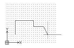
The example below shows the grid set to the drawing bounds and the snap grid set to the grid display spacing.